
Overview
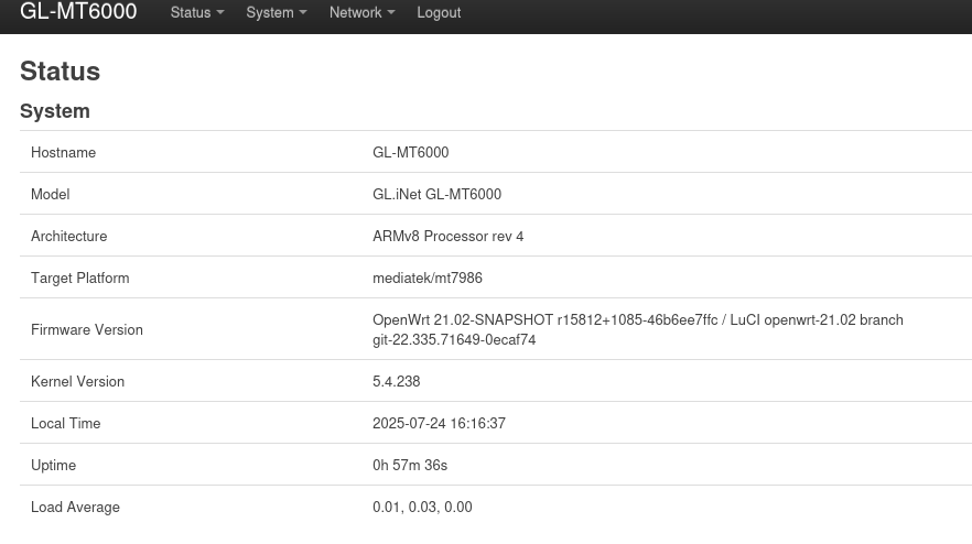
Setting up VLANS on my FLINT 2 router using OpenWRT and the LuCI GUI for Home Assistant and network security. The Flint 2 router comes with a forked version of OpenWRT 21.02.
Most of the setup for VLANs is the same as a Vanilla OpenWRT install minus a few steps at the end where you will need to directly change the /etc/config/wireless file.
I will be setting up 4 VLANS.
| VLAN ID | Purpose | IP | LAN ports |
|---|---|---|---|
| 1 | main VLAN | 192.168.8.x | 1-4 |
| 10 | NVR for Cameras | 192.168.10.x | 5 |
| 20 | IOT | 192.168.20.x | no ports WIFI only |
| 30 | Work | 192.168.30.x | no ports WIFI only |
I also need to create firewall rules to allow my main VLAN, where my Home Assistant box will be sitting on, to be able to push to IOT and NVR network but not allow those VLANS to initiate the transaction
Lastly, I need to ensure that mDNS is enabled using with Avahi-daemon, so that my Home Assistant can discover IOT devices across VLANs. This whole process can be done through SSH or the LuCI web GUI. This is my first time setting up VLANs on a home network so I am going to use the web UI.
1. Define Bridge VLAN Filtering on br-lan
Log into your Flint 2 router. GLINet defaults to 192.168.8.1. Then navigate to SYSTEM > Advanced Settings > Go To LuCI. Alternatively you can go straight to the LuCI webUI at http://192.168.8.1:8080/cgi-bin/luci/.
Once in the LuCI Web UI:
- Go to Network > Interfaces > Devices.
- Find br-lan and click “Configure”.
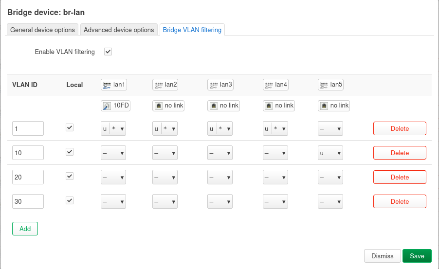
- Go to the “Bridge VLAN filtering” tab.
- Check “Enable VLAN filtering”.
- Configure VLAN 1 (Main Network):
- Select “Add” at the bottom and input “1” for main VLAN
- Check Local (CPU access).
- For lan1, lan2, lan3, lan4 (your Main Network ports): set them as Untagged (U) and Primary VLAN ID (*).
- For lan5 (NVR VLAN port): set as “Do Not Participate” (-).
- Add VLAN 10 (NCR):
- Click “Add”.
- VLAN ID: 10
- Check Local.
- For lan1, lan2, lan3, lan4. set as “Do Not Participate” (-).
- For lan5, se as Untagged (U).
- Add VLAN 20 (IoT):
- Click “Add”.
- VLAN ID: 20
- Check Local.
- For lan1, lan2, lan3, lan4, lan5: set as set as “Do Not Participate” (-) (No wired Work devices).
- Add VLAN 30 (Work):
- Click “Add”.
- VLAN ID: 30
- Check Local.
- For lan1, lan2, lan3, lan4, lan5: set as set as “Do Not Participate” (-) (No wired Work devices).
- Click “Save”. (Do NOT “Save & Apply” yet).
2. Create and Configure New Interfaces
- Go to Network > Interfaces.
- Edit lan Interface (Main Network):
- Click “Edit” next to the lan interface.
- In “General Settings”, set Device to Software VLAN device: “br-lan.1”. This associates VLAN 1 with the interface.
- Keep its IPv4 address (e.g., 192.168.8.1 for Flint 2).
- Click “Save”.
- Add new interface for NVR:
- Click “Add new interface…”.
- Name: nvr
- Protocol: Static address
- Device: Software VLAN: br-lan.10
- Click “Create interface”.
- IPv4 address: 192.168.20.1
- IPv4 netmask: 255.255.255.0
- DHCP Server tab: Click “Setup DHCP Server”.
- Firewall Settings tab: Create a “new zone” named “nvr_zone”.
- Click “Save”.
- Add new interface for IoT:
- Click “Add new interface…”.
- Name: iot
- Protocol: Static address
- Device: Software VLAN: br-lan.20
- Click “Create interface”.
- IPv4 address: 192.168.10.1
- IPv4 netmask: 255.255.255.0
- DHCP Server tab: Click “Setup DHCP Server”.
- Add new interface for Work:
- Click “Add new interface…”.
- Name: work
- Protocol: Static address
- Device: Software VLAN: br-lan.30
- Click “Create interface”.
- IPv4 address: 192.168.30.1
- IPv4 netmask: 255.255.255.0
- DHCP Server tab: Click “Setup DHCP Server”.
- Firewall Settings tab: Create a “new zone” named work_zone.
- Click “Save”.
3. Configure Wireless SSIDs for IoT and Work
- Go to Network > Wireless.
- Find your existing main Wi-Fi SSID and click “Edit”.
- In “Interface Configuration” tab, ensure Network is set to lan. Click “Save”. (This should already be set, but good to double check.)
- Click “Add” next to the Generic 802.11bgnx (2.4GHZ) wireless device, to create a new SSID for IoT.
- ESSID: MyHome-IoT (or similar)
- Network: Select the iot interface you just created.
- Configure your desired “Wireless Security” (WPA2/WPA3 recommended).
- Click “Save”.
- Click “Add” next to the Generic 802.11anacax (5.0GHZ) wireless device, to create a new SSID for Work.
- ESSID: MyHome-Work (or similar)
- Network: Select the iot interface you just created.
- Configure your desired “Wireless Security” (WPA2/WPA3 recommended).
- Click “Save”.
4. Configure Firewall Rules for Isolation
This is crucial for security.
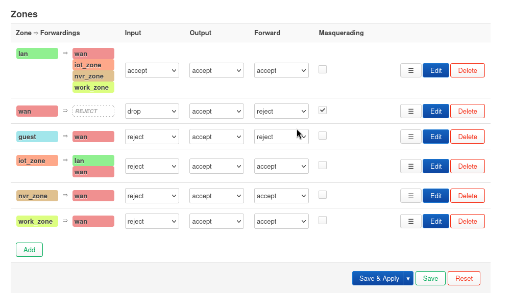
- Go to Network > Firewall.
- Review your Zones:
- lan Zone (Main Network):
- Input: Accept
- Output: Accept
- Forward: Reject (initially, then add specific forwards as needed is best practice, for now I have accept.)
- Allow forward to destination zones: WAN (Internet access).
- Allow forward from source zones: (Usually empty or WAN for traffic initiated from WAN to LAN if you have port forwards) * iot_zone:
- Input: Reject (unless you need to manage IoT devices via router from IoT VLAN, then change to Accept)
- Output: Accept
- Forward: Reject
- Allow forward to destination zones: WAN (for internet access) and Lan for mDNS. * nvr_zone:
- Input: Reject
- Output: Accept
- Forward: Reject
- Allow forward to destination zones: WAN (if cameras need cloud access, mine are wired and do not). Do NOT add lan or iot_zone here. * work_zone:
- Input: Reject
- Output: Accept
- Forward: Reject
- Allow forward to destination zones: WAN (for internet access). Do NOT add lan or iot_zone or nvr_zone here.
![image]()
- Add Specific Traffic Rules (Important!):
- You’ll need rules to allow your lan devices (like your Home Assistant PC) to initiate connections to your iot_zone and nvr_zone if HA needs to control/monitor them.
- Click “Add” under “Traffic Rules”.
- Rule 1: Allow Main LAN to IoT (initiated from Main LAN)
- Name: LAN_to_IoT
- Protocol: Any
- Source zone: lan
- Destination zone: iot_zone
- Action: Accept
- Optional: If you only want specific services/ports, change Protocol and Destination port. E.g., TCP/UDP for specific ports. * Rule 2: Allow Main LAN to nvr (initiated from Main LAN)
- Name: LAN_to_nvr
- Protocol: Any
- Source zone: lan
- Destination zone: nvr_zone
- Action: Accept
- Optional: If nvrs only serve specific ports (e.g., RTSP port), refine this rule to TCP and that port. * Rule 3: Basic DHCP for new VLANs (if Input on zone is Reject). This will be a separate rule for each VLAN you create:
- Name: Allow_“VLAN Name”_ DHCP
- Protocol: UDP
- Source zone: vlan_zone
- Source port: 68
- Destination zone: Device (input)
- Destination port: 67
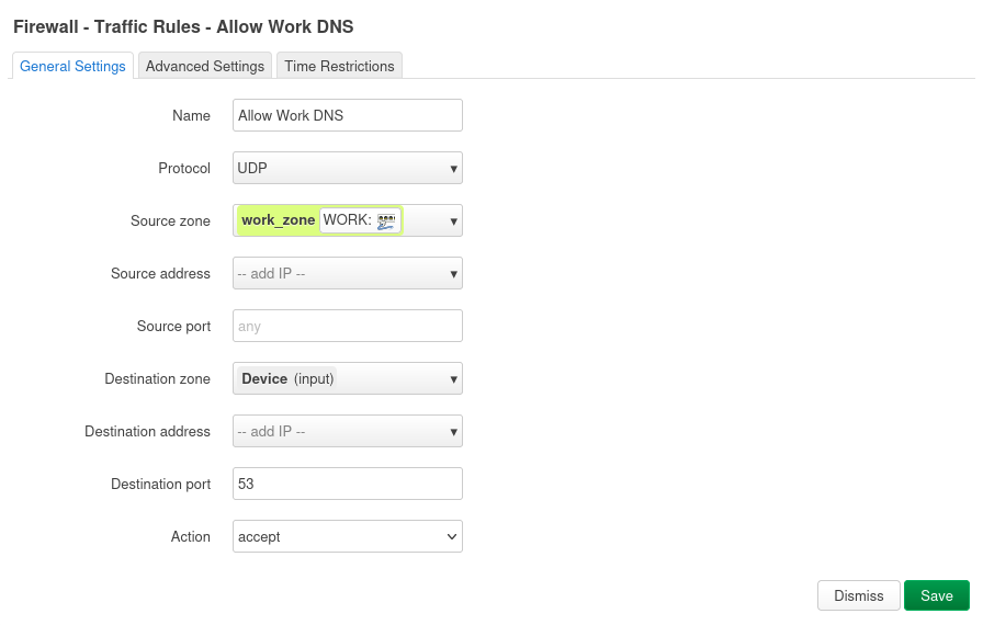
- Action: Accept * Rule 4: Basic DNS for new VLANs (if Input on zone is Reject). This will be a separate rule for each VLAN you create:
- Name: Allow_“VLAN Name”_ DHCP
- Protocol: UDP
- Source zone: vlan_zone
- Source port: any
- Destination zone: Device (input)
- Destination port: 53
- Action: Accept
![image]()
![image]()

5. Save and Apply All Changes. SSIDs will probably be broken.
- After all the above steps, click the large “Save & Apply” button.
- The router will process the changes. You may lose network connectivity for a minute or two.
- Go back to Network > Wireless.
- You may see that the SSIDs you created for your VLANs are enabled but show an error of “wireless is not associated.”
- This is where you will need to SSH to your router.
- run
ssh [email protected]. Enter password. - run
vim /etc/config/wirelessand find the interface associated with your VLAN SSIDs. Your SSID name will be under “option ssid”. - After the “option key” line insert
option ifname 'raN'where N <= 3 for 2.4 GHz device or insertoption ifname 'raxN'where N <= 3.
IOT Interface (2.4 GHZ)
1
2
3
4
5
6
7
8
9
10
config wifi-iface 'wifinet4'
        option device 'mt798611'
        option mode 'ap'
        option encryption 'psk2'
        option key 'secret_key'
        option ifname 'ran2'
        option network 'IOT'
        option wmm '0'
        option macaddr 'DE:9F:27:0C:E7:EF'
        option ssid 'IOT'
Work Interface (5 GHZ)
1
2
3
4
5
6
7
8
9
config wifi-iface 'wifinet5'
        option device 'mt798612'
        option mode 'ap'
        option encryption 'psk2'
        option key 'secret_key'
        option ifname 'rax2'
        option network 'WORK'
        option ssid 'Work'
        option macaddr '1A:34:E7:D4:E3:55'
- Save the file.
- Reboot the router and it should be good to go.
6. Test Firewall Rules
Test Thoroughly!
- Connect your Home Assistant PC to LAN1, ensure it gets a 192.168.1.x IP and has internet access.
- Connect your NVR to LAN2, ensure it gets a 192.168.20.x IP and has internet access (if needed).
- Connect a device to your IoT Wi-Fi, ensure it gets a 192.168.10.x IP, has internet access, and cannot access devices on the 192.168.1.x or 192.168.20.x subnets directly (unless explicitly allowed by a firewall rule for specific purposes).
- Connect a device to your Work Wi-Fi, ensure it gets a 192.168.30.x IP, has internet access, and cannot access devices on other internal VLANs.
- Test that your Home Assistant PC can communicate with devices on the IoT and Camera VLANs as intended.
7. Add mDNS with Avahi Daemon
- Access your Router’s Admin Panel:
- go to http://192.168.8.1 (or your router’s configured IP).
- Log in with your administrator password.
- Install the Avahi Daemon Plugin:
- Navigate to Applications > Plug-ins.
- In the search bar, type avahi-dbus-daemon.
- Find and install avahi-dbus-daemon. (There might be other Avahi-related packages, but this is usually the primary one needed).
- This is pre-installed on Flint 2 so there is nothing for me to do here.
- SSH to the router.
ssh [email protected]. Enter password. - Configure Avahi to Enable Reflector Mode:
- Once logged in via SSH, you need to edit the Avahi configuration file.
- Open the file with vim or nano
vi /etc/avahi/avahi-daemon.conf. - Look for the line enable-reflector=no.
- Change it to:
enable-reflector=yes - Save the changes and exit the editor:
- vi: Press Esc, then type :wq and press Enter.
- nano: Press Ctrl+X, then Y to confirm save, then Enter.
- Restart the Avahi Service:
- After modifying the configuration, restart the Avahi daemon for the changes to take effect:
/etc/init.d/avahi-daemon restart
- Add Firewall Rules to Allow mDNS traffic between IoT and Main Network.
- Same steps as before when creating firewall rules.
- Rule 1: mDNS IoT to Main:
- Name: Allow mDNS IoT to Main
- Protocol: UDP
- Source zone: iot_zone
- Source port: 5353
- Destination zone: lan
- Destination Address: 224.0.0.251
- Destination port: 5353
- Action: Accept * Rule 2: mDNS Main to IoT:
- Name: Allow mDNS Main to IoT
- Protocol: UDP
- Source zone: lan
- Source port: 5353
- Destination zone: iot_zone
- Destination Address: 224.0.0.251
- Destination port: 5353
- Action: Accept
- Verify
- Check Avahi service status:
/etc/init.d/avahi-daemon status
- It should show as running. * Test mDNS discovery: From a device on one of your networks/VLANs, try to discover an mDNS service on another VLAN. For example, if you have an AirPrint printer on a guest network and your phone on the main network, try to print. You could also use a tool like “Discovery” on macOS or “Bonjour Browser” on Windows/mobile to see if devices are appearing.
- Check Avahi service status: